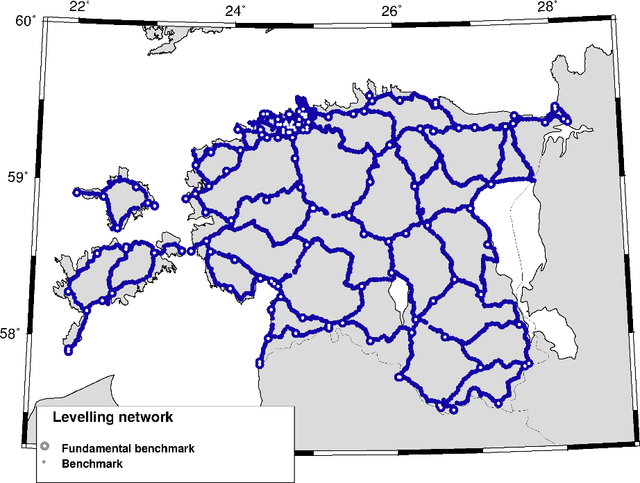
Levelling Network
The reconstruction of the Estonian levelling network took place in 2003-2016. The levelling network consists of levelling lines forming 15 polygons on the mainland and 2 on the islands. Additional smaller polygons are located on the periphery of the Estonian mainland. The levelling network includes all the levelling lines of the first and second order levelling networks and a part of the levelling lines of the Tallinn levelling network (2003-2009). The overall length of the levelling lines is 4238 km, the average distance between the benchmarks is 1.4 km, and the levelling network consists in total of 3144 benchmarks. Digital levels and invar rods were used for levelling. All levelling lines were measured forward and backward according to the first order levelling network measurement methodology. Measurements were only made on spherical benchmarks.
The Estonian levelling network was adjusted in two stages. First, the European Unified Levelling Network (together with data from the reconstructed Estonian high-precision network) was adjusted. The European Computing Center obtained an average accuracy estimate of ± 0.228 kGal · mm / √km for the Estonian levelling network and an average accuracy of ± 13.9 mm for heights.
For the adjustment of the Estonian levelling network, one benchmark, the Põltsamaa Fundamental Benchmark (H = 55.21140 m), was fixed. The height of the initial benchmark was obtained from the adjustment of the European levelling network. This adjustment ensures the best compatibility between the levelling networks of Estonia and neighbouring countries. The hydrodynamic levelling results of 2011 were used to link the mainland’s network to the islands of Western Estonia. The land uplift model NKG2005LU was used to transfer the levelled heights to the epoch 2000. As a result of the adjustment of the national levelling network, the accuracy of the heights was estimated at ± 1.7 mm. In Estonia, the heights of the EVRS system are denoted by the abbreviation EH2000. The calculation of EH2000 heights was based on the EVFR2007 solution (Solution 201703 / NKG2005LU).
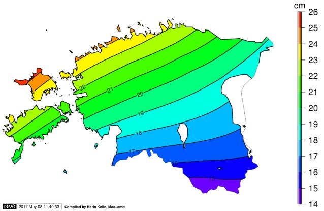
Transformation parameters between BK77 heights and EH2000 heights
The BK77 and EH2000 transformation parameters were calculated as a model surface using 68 height differences between the BK77 and EH2000. The model surface allows BK77 heights to be recalculated to EH2000 heights and vice versa. The transition model’s step is 1' x 0.5', area is B = 57º 20'... 60º 00' and L = 21º 20'... 28º 40'.